克服汽車系統(tǒng)HB LED集成方案的技術(shù)瓶頸
Abstract: High-Brightness LEDs (HB LEDs) provide a number of advantages over traditional lighting technologies in automotive applications. They are more environmentally friendly, improve safety, enhance the look and style of vehicles, and have longer life. But designing a highly efficient, low-cost, high-performance HB LED-based lighting solution presents many challenges. A new generation of multistring LED drivers makes it easier to meet all those challenges.
A similar article appeared in the July/August, 2009, issue of Power Systems Design magazine.
Introduction
Today's automobile manufacturers are converting more of their lighting systems from incandescent and CCFLs (cold-cathode fluorescents) to HB (high-brightness) LEDs. These HB LEDs are used for backlighting in navigation and entertainment displays, for internal cabin lights, and for external lighting such as daylight running lights and tail lights. New applications like heads-up displays are also expected to leverage HB LEDs.
First-generation HB LED drivers had some limitations. They did not allow designers to optimize efficiency, minimize external component count, minimize EMI, or achieve a very wide PWM dimming range. The latest generation of multistring HB LED drivers, such as the MAX16814, solves these design challenges in unique ways by allowing intercommunication between their switching and linear control sections. This article presents an example design for daylight running lights or heads-up displays.
Why HB LEDs?
HB LEDs are gaining popularity in the automotive world, quite simply because they offer automobile designers many advantages. HB LEDs are a more environmentally friendly technology than other lighting technologies—they have superior energy efficiency and do not contain mercury, thus they release fewer harmful chemicals when recycled. HB LEDs can also improve car safety. They turn on and off faster than incandescent lamps, which is why they are commonly adopted for brake lights.
HB LEDs allow car makers greater freedom in designing the style or "look" of their vehicles. The LEDs are small, directional sources of light that require almost no depth behind the panel. Designers can create light arrays of any shape thanks to the small size and directionality of the light emitter. As a small emitter of light, they are ideal for applications with light guides.
Finally, with lifetimes of 50,000 hours or more, HB LEDs have a much longer life than any other lighting technology. This makes them ideal for any application where the light remains on for an extensive amount of time. Daytime running lights are an ideal example.
HB LED technology is also important for advancing new applications like heads-up displays. The ability to dim LEDs over a very wide range, depending on the intensity of the ambient light, is particularly useful. Here is where PWM dimming becomes so important.
When you understand the "why" of HB LEDs, it is no surprise that their use is becoming prevalent in automobile design today. Their applications include brake lights and rear lights; front lights (daytime running lights, position lights in mid-to-high-end cars, and high- and low-beam lights in very high-end vehicles); and interior lights, where RGB LEDs allow control of light color, giving a unique style to the vehicle. The application of HB LEDs in navigation, entertainment, and cluster display backlights is also becoming mainstream (Figure 1).
Figure 1. HB LEDs are making inroads into every automotive-lighting application, from headlamps to brake lights and everything in between.
Challenges of Designing with HB LEDs
Of course, the integration of HB LEDs into automotive applications presents challenges. Keeping cost as low as possible is an immediate concern. LED lamps are, in general, a more costly lighting solution than other technologies (e.g., incandescent, halogen, CCFLs) at the component level. For this reason, the cost of LED solutions at the system level must be minimized to improve the market penetration of this technology. To reduce the solution cost, the number of components required by the driver must be kept as low as possible. This approach also improves reliability, because each component on the PCB is a potential failure point in the system.
Another challenge is efficiency. High energy efficiency is increasingly important in cars, especially hybrid vehicles. Efficiency must be optimized to reduce power dissipation (heat). Automotive components work in a hot environment, with maximum ambient temperatures of +105°C for parts in the engine compartment or +85°C for many other applications. LEDs generate considerable conducted heat (they do not irradiate energy in IR or UV bands like other kinds of lights), and so their power dissipation also contributes to raising the ambient temperature. Thus, it is essential to minimize power dissipation from the LED driver to avoid overheating the IC or other components in the driver module.
To no surprise, automotive environments have challenging requirements for EMI. The lighting subsystem can interfere with other vehicle subsystems, of which the AM radio is usually the most sensitive. This can be an issue since LEDs require electronic switching or linear driver circuits that can cause EMI noise (especially switching circuits) or EMI susceptibility. The driver circuits can also cause unpleasant audible noise, for example from ceramic capacitors.
Benefits of Multistring LEDs
A number of automotive applications require LEDs to be placed on multiple strings. A string is a group of LEDs connected in series, therefore having the same current. The form factor of displays makes it easier to place LEDs on multiple strings for their backlights. Having multiple strings, moreover, improves fault tolerance. If one LED breaks, only the LEDs in that particular string fail to light, not all of the LEDs in all the strings. For safety reasons, multiple strings also limit the voltage of an individual LED string. As an example, a single LED string with 80V total voltage can be split into two strings of 40V each, thus reducing the risk of injury to someone who accidentally touches the LED contacts or wires.
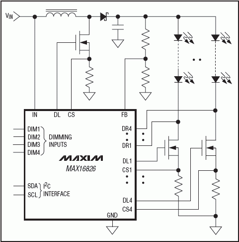
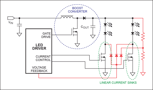
Multistring drivers, therefore, offer an obvious, overriding advantage: just one IC is required for many strings. For example, a multistring configuration could include the LED strings; a single boost converter, which converts the input battery voltage into a higher voltage required by the LED strings; and multiple, linear current sinks that set the current of each string (Figure 2). 
Figure 2. A basic multistring driver configuration uses a single chip to control the current to multiple LED strings. Components shown in red can be added to perform adaptive voltage optimization while the boost converter and linear current sinks work independently.
Compared to the solution with multiple switching converters, this solution has fewer components and lower cost (a single inductor and fewer shunt capacitors are needed). Compared to having a single-string driver and directly connecting the LED strings in parallel, there is an advantage in the current balancing among the strings. If multiple strings are directly connected in parallel, the current splits unevenly among them because some LEDs have higher forward voltage than others. Moreover, since the LED forward voltage decreases with increasing temperature, this current imbalance can cause thermal runaway. The string with more current is hotter, its forward voltage decreases, so it draws even more current, becomes even hotter, and so on. The current imbalance grows, and one or more strings carrying greater current can fail. Finally, if the LED strings are simply paralleled, the driver controls only the total current. When one string fails and opens, its current is transferred to the other strings, which can then fail because they are overdriven. None of these problems happens with the current-balancing solution in Figure 2.
There is, admittedly, a limitation of the topology of Figure 2: it uses linear MOSFETs to set the string currents. To keep the temperature of those MOSFETs low, the voltage drop across them must be as low as possible, but high enough to keep them in their saturation region. The boost output voltage must then ideally be:
VBOOST = max(VSTRING,I) + VSAT
Where VSTRING,I is the total forward voltage of string I, and VSAT is the VDS needed for the linear MOSFETs to remain in saturation. An LED driver that sets VBOOST to its ideal value is said to perform AVO (adaptive voltage optimization).
AVO is further complicated because LEDs must be PWM-dimmed in most applications. They must be turned on and off with a certain duty cycle, and that is done by turning their linear current sinks on and off. But then, what should the boost converter do when all the LED strings are turned off? This is another design problem with many possible answers and some limitations, as we will discuss.
Problems with Traditional Multistring Drivers
Traditional multistring LED driver solutions using the topology of Figure 2 include a boost switching converter and multiple current sinks that work as separate entities. When those drivers are used, implementing AVO requires some external components which, in turn, can cause their own set of issues.
One problem is that an external circuit must detect which LED string has the highest forward voltage (or the lowest cathode voltage). This can be done with a few diodes, such as the structure marked red in Figure 2. This solution causes the board area and solution cost to increase.
Another concern is what happens when an LED fault occurs. If an LED fails and opens the circuit, the voltage at the cathode of that string falls to zero; the diode circuit detects that LED string as the one with the highest forward voltage. Consequently, it tries to provide enough voltage for that string and starts increasing VBOOST. This results in multiple possible problems. An increase in the voltage is applied to the current-sink MOSFETs of the other strings, which can then cause them to fail. Or, the voltage increase can trigger the output overvoltage protection (OVP) of the boost converter (if present) which shuts it off, thus turning off all the strings.
A third issue is what this circuit should do when the LEDs are PWM-dimmed. When the LEDs are off, the diode circuit has no string voltage as a reference to set VBOOST. A possible solution is to add another diode connected to the boost output through a divider, as done with the circuitry marked red in Figure 2. This diode turns on when the LEDs are off, and sets VBOOST to a predetermined voltage. The obvious problem with this solution is that the output voltage of the boost converter has a high ripple at the PWM dimming frequency. (See Figure 3.) This voltage rippling can cause EMI noise which, as mentioned above, is a serious problem for automotive applications. Voltage ripple can also cause unpleasant audible noise from the output capacitor, COUT. Pic/2009-10/200910317528463.gif">
Figure 3a. With a traditional driver performing PWM dimming and utilizing the external circuitry of Figure 2, the VBOOST changes between the on- and off-time of the LED current. The result is a noisy voltage rail.
Figure 3b. With a new-generation driver, the boost converter stops switching during the off-time of the LED current. Thus, the converter's output is maintained by its output capacitor and the voltage only slightly decreases due to leakage currents.
Advances in the New Generation of Multistring Drivers
New-generation multistring drivers have greatly improved performance. Instead of having the converter and current sinks work independently, they allow communication between the boost switching converter and the linear current-sink portions of the design. Thus, these new multistring drivers address the three design issues described above.
In these new-generation drivers, the IC internally senses the LED string voltages, i.e., the voltages at the drains of each current-sink MOSFET. The IC then selects the lowest string voltage with an internal diode- or analog-switch-based circuit (Figure 4). In this way, the number of external components and the solution cost are substantially decreased. 
Figure 4. In a new-generation HB LED driver IC, internal communication between the LED sink drivers and the boost converter allows more effective control and eliminates many of the issues encountered by older drivers.
This intercommunication solves the disruptive problem when one LED in a string fails and opens the circuit. If an LED fault happens in this new design, the VBOOST starts increasing. Once this voltage reaches an OVP threshold, the faulty string is identified, disabled, and removed from the AVO control loop. The other strings continue working normally. Most importantly for the user, the effect of the LED failure is merely reduced brightness of light instead of a complete turn-off.
There are some concerns regarding what the LED driver's switching converter should do when the LEDs are PWM dimmed. The integration of the switching and linear sections allows a different and quieter solution than the one described in Figure 2. Now the boost converter can be "frozen" when the LEDs are off, as in Figure 3b. While the converter stops switching, the switching power MOSFET is kept open and the compensation circuitry is opened as well. At this point, the compensation capacitor retains its charge, which is the state of the compensation loop. VBOOST is then retained by COUT, which is not discharged because the LEDs are off. The only discharge current from COUT is leakage current. When the LEDs come back on, the converter restarts switching with minimal ripple. With this solution, VBOOST remains almost constant throughout the PWM dimming cycle, thus considerably reducing both EMI noise and audible noise from the output capacitor.
The only limitation of this solution is that the PWM dimming on-time must be longer than a few (e.g., three or four) switching cycles. Longer on-time is needed so that the boost converter can recharge COUT with the charge that leaked off during the off-time. This limits the minimum duty cycle that can be achieved.
Applying the New-Generation Drivers
In a car, both the daytime running lights and heads-up displays have similar performance demands: they are on whenever the car is running, and need high reliability/redundancy to ensure that they are always available. By using a new-generation multistring driver such as the MAX16814, the required high reliability can be achieved while component count is minimized, thus improving reliability with fewer parts to fail and reducing system cost.
These life-critical applications are also similar in their system requirements: operation over a wide input voltage range; sustaining voltage peaks (load dump) of typically up to 40V from the car battery; and low EMI generation.
Fault tolerance is essential. It is critical that the LED light never shuts off completely in case of a fault. Using a multistring approach in combination with the MAX16814 assures that if one LED opens or shorts, only that string is shut down; other strings will continue to work normally. Additionally, because of its fault output, the MAX16814 can signal back to the driver that one LED failed (Figure 5).
Heads-up displays also need a very wide (1000:1 or more) PWM dimming range. The MAX16814 integrates a unique PWM dimming solution* that eliminates ripple at VBOOST (at the dimming frequency), thus minimizing EMI and audible noise. This MAX16814 solution is similar to the approach used in Figure 3b, but it also allows a very wide PWM dimming range of 5000:1 at 200Hz. This dimming range is wider than any similar product, and overcomes the minimum on-time limitation mentioned above.
The MAX16814 can drive 4 LED strings with up to 150mA per string, and provides the requisite intercommunication between the switching and linear control sections. This chip thus dramatically reduces external component count. Additionally, the MAX16814 includes a complete set of fault-protection and detection features. If any string has LED open or short failures, that string is disabled and the fault condition is signaled to the system. Finally, this IC is a full-featured automotive product, with a 40V maximum input voltage capability and a -40°C to +125°C operating temperature range.
Figure 5. This is an example of a complete automotive design for a heads-up or running-light driver subsystem, including all the external components and an input EMI filter. Because of the low noise of the MAX16814, the EMI filter component value can be kept low.
When designing an HB LED-based system, many tradeoffs are possible, such as component count, efficiency, and reliability. Table 1 compares various multi-LED driver solutions to help designers select the best approach for their application.
Table 1. Summary of HB LED Driving Approaches
| Solution | External Components | Efficiency | Current Balancing | Response of Other LED Strings if One Opens | EMI and Noise with PWM Dimming | PWM Dimming Range |
| Multiple Switching Converters | Many | High | Good | They continue to work | Low | Wide |
| LED Strings Paralleled, Single-String Driver | Very few | Medium | Bad | Their current increases; they can fail | Low | Wide |
| Independent Boost Converter and Linear Sinks, Without AVO | Few | Low | Good | They continue to work | Low | Wide |
| Independent Boost Converter and Linear Sinks, with AVO | Some | Medium | Good | They can turn off | Noise at dimming frequency | Wide |
| Internal Communication Between Boost Converter and Multiple Linear Sinks | Few | Medium | Good | They can continue to work | Low | Limited |
| Maxim MAX16814 | Few | Medium | Good | They continue to work | Low | Wide (5000:1 at 200Hz) |
Newer generation LED drivers lower component count. Moreover, by leveraging the intercommunication between switching and linear sections, they provide more cost-effective solutions, higher efficiency, and improved features including better fault protection and detection. The MAX16814 is a multistring driver that provides all of these advantages plus a wider PWM dimming range than any similar product available in the market.
 電子發(fā)燒友App







評(píng)論